
Why source electronic components from Us
Estimate Bom Cost, Pls send bom list to Sales@pcba360.com, You will get quote very soon.
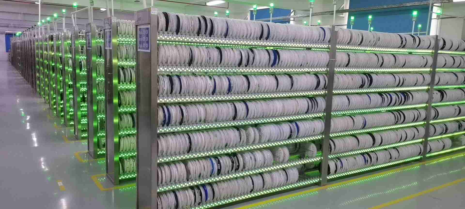
XDF is a leading hybrid distributor of electronic components in Shenzhen. XDF supply various active components (IC-integrated circuits, memory chips, diodes, transistors, etc.), passive components (capacitors, resistors, inductors, etc.), and electromechanical components (connectors, switching devices, etc.), or other hard finding special electronic parts.
We are some brands authorized agent,also cooperate with different autorized agents and distributors, and Strive to improve our advantages of more electronic components continuously. We serve original equipment manufacturers (OEM), original brand manufacturers (OBM), electronic product contract manufacturers, EMS (Electronics Manufacturing Service) providers, and design houses (Design House) to provide comprehensive Supply chain solutions for electronic components.
Our business covers industrial control, military, security, LED lighting, medical equipment, automotive electronics, instrumentation, consumer electronics, optoelectronic coupling, power management, communication, network and computer circuit components, smart homes, sensing instruments, subway high-speed rail, automation, etc. We can provide customers in various fields, including spot purchases, bill of materials matching, lower purchase costs, and small-batch purchases.
Distribution: XDF has many years of operational experience in the electronic components industry , has an excellent cooperative relationship with many well-known brand manufacturers and agents, and acts as an agent to distribute well-known brands at home and abroad.
Genuine parts at a fair price: Well-known brand manufacturers, agency direct supply, and first-hand supply. It is guaranteed that you will receive authentic and original products. No fake or shoddy. All brands and products are priced competitively.
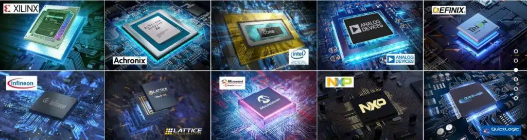
Superiority products: In-depth cooperation with many broad channels and leading international imported for well-known brands: integrated circuit (IC), MOS field effect transistor, diode, Schottky, voltage regulator, SCR, optocoupler, IGBT/power tube sticker Chip LED capacitor/resistance/inductance, connector, etc.
Fast shipping: Stable channels and long-term supply. We hold a large amount of inventory, inquiries, and orders. Components can also be shipped quickly. The conventional supply is sufficient, and the order will not be delayed. Professionals IQC control and strictly inspect every component to ensure that the product is genuine and original.
Quality services: Superior products, rich experience, knowledge of trending market data, provide cost-effective services, and the fastest product inventory acquisition.
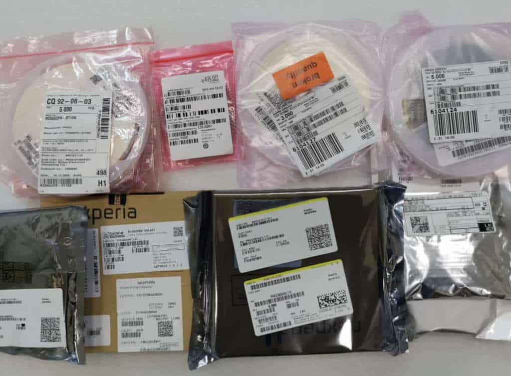
Full Traceability:We operate full supply chain management, only purchasing from franchised distributors, or with the component manufacturers directly. This ensures that we attain the best opportunities and optimal price points, all suppliers are trusted and reliable, and the procurement process is fully-traceable.
Bill of Materials (BOM) list quotes: Has many years of experience in distribution and inspection. Provide customers with the most reliable products and services. Provide product information or BOM to us, and you will promptly receive the product quotation and delivery date.
As a PCB Assembly manufacturer,we know electronic components well ,we know how important each component is .
BOM Management And COST
As a buyer or program manager, you have a lot of work on your plate. You need one supplier to help simplify your work and be as efficient as possible. XDF electronic Components now features our Bill of Materials (BOM) Management Team to help.
✔ Send your lists from excel, csv, or txt to get started quickly.
✔ Add part numbers to existing BOMs on the fly as changes come up.
✔ Leverage our library of valid part numbers to scrub and validate the items on your BOM.
✔ See real-time costs and lead time for your entire list.
✔ Place orders with ease and repeatedly as your production needs require.
✔ Manage and keep your BOMs current as you make changes.
✔ Send your BOMs, and XDF’s customer support will handle it for you.
XDF is proud to offer low-cost electronic components procurement in China by leveraging convenient market availability for all types of requirements. We have grown to become the most preferred turnkey PCB assembly house for such services because of our firm knowledge and understanding of the global procurement market. We readily source affordable electronic components from our trusted distributors.
More than 10 years, XDF has developed solid relationships with most distributors worldwide, which has enabled us to source requisite quality parts from local vendors, authorized suppliers, and manufacturers by following a rigorous procurement process.
We have created well-organized and accurate procurement methods for electronic components, allowing us to source only the required parts and those suitable for satisfying customer requirements. This streamlined process has helped us to purchase the highest quality parts from the most reliable distributors.
Electronic parts procurement is not exclusively about getting the best possible price but also sourcing high-quality components. Clients are sometimes worried about the quality of components sourced in China. Still, with XDF’s support, our customers can rest assured due to our sourcing experiences and inspection techniques. We update our users about the stringent quality methods followed, despite sourcing the parts from branded suppliers in China, which has further enabled us to pass the benefits to our consumers.
As we purchase high-quality parts from known distributors at the most affordable rates of any turnkey PCB service solution, we pass on the benefit of low cost to our clients. Our clients get the dual benefit of competitive sourcing of the best components, along with time to give the required attention to their primary business.
We have a strong network in China with local suppliers to obtain the mandatory components and meet the customer-specific demands at a relatively low cost. This has also led to an advantage in handling charges, which is further passed on to the end-users. You can also reach us at sales@pcba360.com for additional information regarding the procurement of unique IC components.
We have our own distinctive and comprehensive IC sources to meet the ever increasing specifications of our clients. We typically procure ICs in Taiwan, Korea, Japan, and other regions across Asia at a reasonably low price compared to other Turnkey PCB assembly houses. This has further helped to win the trust of our customers for us.
ELECTRONIC CIRCUIT BOARD COMPONENTS:
In today’s world of modern technologies, we see high tech PCBA 2devices all around us, from our houses to our offices, work places, roads, market places, education institutions everywhere we see modernization of technology and key to all these technologies is advancement in Electronics Industry.
What is Circuit Board:
A circuit board also known as PCB (Printed Circuit Board) is platform made of silkscreen, solder mask, copper, and pcb substrate. The substrate is FR-4 composite material made of woven fiber glass cloth with an epoxy resin binder which is fire retardant that is why named FR (Fire Retardant).
The components solder upon PCB to make it function as electronic device. The assembly is known as PCB Assembly or PCBA. The PCB is designed in a particular CAD software like ALTIUM, ORCAD, EAGLE etc. These software can generate the circuit design (Schematics) and then circuit designer can then layout PCB in this CAD software. This software then generates “GERBER” file that can be fed into PCB fabrication machines to actually print tracks and fabricate PCB.
Electronic Devices and Equipment:
There are various electronic devices and equipment that contains electronic components. Some of them are Linear Power Supplies, Switch Mode Power Supply, Amplifier, Filters, Oscillators, Oscilloscope, Function Generator, Digital Multi-Meter, Network Analyzers, Spectrum Analyzers etc. These are the laboratory equipment that are used to develop other electronic products like consumer electronics , industrial electronics, automobile industry, Military and Defense products.
Applications of Electronic Devices:
Some of the consumer electronic products include LED TV, LCDs, Android Mobiles, Telephones, Wearable electronics, gadgets, etc. Industrial products like PLC, Relays, Switches, Sensors, Actuators, Servo Motor drives, DC motor conveyer belt electronics etc. Automobile electronics include car charger, AM/FM radio electronics, GPS tracker/navigator, LED lights controls, relays, valves, fuses etc
How To Design a Circuit:
The electronic circuit design is based on the requirements from the customer. There are two main categories of components. 1- Active Components and 2- Passive Components
The active components are those that need power source to operated like OPAMPs, transistor, MOSFETs etc while the passive components are those that dissipate energy like resistors, capacitors, inductors etc.
Electronic Components:
Example 1: (Relay Switch Circuit)
circuit
Here in this circuit, we have selected NPN type BJT transistor BC337. This transistor is connected in common emitter mode and 1KΩ resistor is the base resistor used to control the base current . The 10KΩ resistor is used to tie the Base of BC337 to ground (GND) so that when trigger at input positive edge trigger is given, then the transistor will go in saturation and conducts through Collector and Emitter to short the GND to Relay coil. Hence Coil will energize and Normally Close (NC) the contacts of Relay.
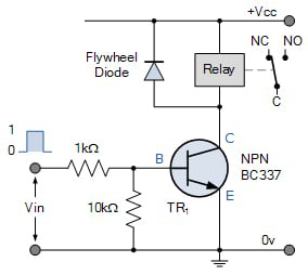
On the other hand if the trigger is not applied transistor will remain in cutoff and C-E junction will remain open and GND is not shorted to coil of relay hence relay will remain in Normally Open (NO)
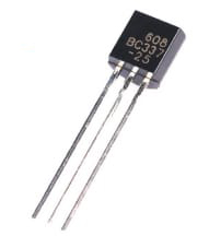
Transistors:
The two main types of transistors are BJT and MOSFET. The BJT transistor is a current controlled device and is commonly used in relay control switches.
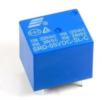
Relay:
The relay is an Electromechanical electronic components, that has a coil and two contacts (NO and NC). This coil when 12VDC is applied the relay will change its state from NC to NO and vice versa
The relay are available in 5V, 12V, 24VDC coils and contacts ampere ranging from 10A to 30 A. So if you have to drive heavy load like water pump, Air Conditioner, Blower, Large Servo Motors, then use high ampere relays otherwise for small loads like bulb, LED lights etc use small relays.
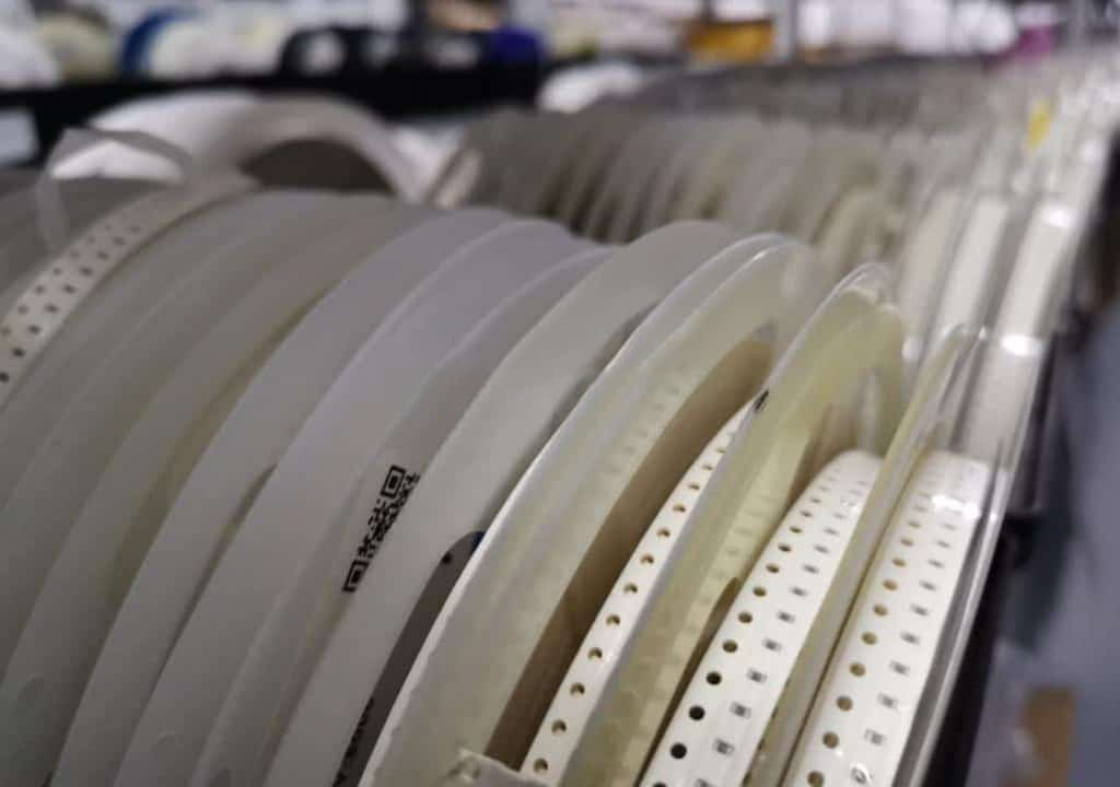
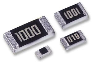
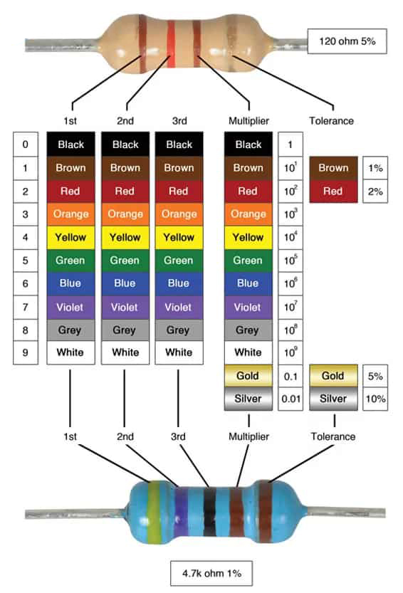
Resistors
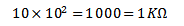
The resistor is used to control the current flow and divide the voltage as required. In our case above, we have used “Voltage Divider Network” that drops the voltage at 1KΩ and pass remaining potential to 10KΩ to the base. The table to recognize and select the proper resistor is given. The resistors are very cheap and available at every electronic store. They are available in SMD and Through hole types.
Example 2: (Power Supply)
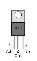
Here in this circuit, we have used adjustable LM317 voltage regulator. The voltage regulator can generate stable DC Voltage output programmed by the two resistors R1 and RV1. Capacitor C3 is the bypass capacitor to connect adjust pin to GND to improve ripple rejection capability. C1,C2,C4 used to eliminate ripple voltage. Diode D5 is used to protect reverse current from output to protect regulator IC.
D1,D2,D3,D4 are full bridge converter to convert AC to DC level. RV1 is trim pot used to set the fixed output voltage.
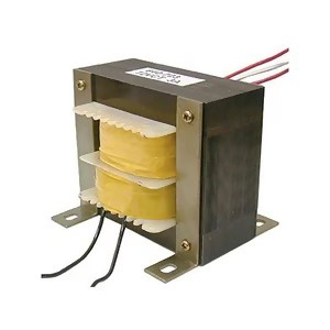
Transformer:
The transformer is the device that converts high AC voltage like 230VAC to 24VAC low voltage to be used by bridge rectifier. The transformer is selected by finding turns ratio according to the primary and secondary voltages.
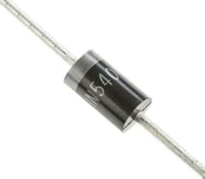
Diode
This is the semiconductor components, used in bridge rectifiers,fly-back / fly wheel purpose. This diode will forward bias and drop 0.7V across it. In semiconductor devices, Silicon is the important ingredient and proper doping will cause the barrier / junction creation.
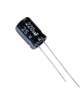
Capacitor:
This passive component, is very common in electronics and used in dual and single power supplies. Main purpose is filtering. In timing circuits, it is used as RC timers. In OPAMP integrators used in feedback loop. The larger the rated voltage and capacitance, the larger the size of capacitor.
If the output voltage is regulated at 24VDC then the output ripple capacitor should be selected at rated voltage greater than 24V like around 100V. Otherwise the capacitor will burst or swollen. The longer lead is positive and smaller lead is negative leg.
Voltage Regulator:
The linear voltage regulators are available under 1A rating and can provide output voltage 1.2V to 438V DC. The voltage regulator is selected to check the least dropout voltage, number of outputs, output voltage polarity, input voltage range and packaging as desired case to case basis.
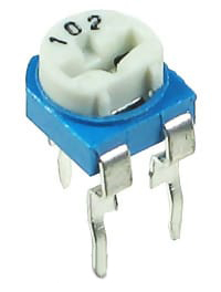
Potentiometer:
The trim pot is widely used in various electronic circuits. It is used in voltage divider circuits, to set the reference voltage in OPAMP comparator circuits, to set the output voltage in adjustable voltage regulators, used in RF circuits for tuning, used in timers to set the value of R in RC timers. The code 102 written means that
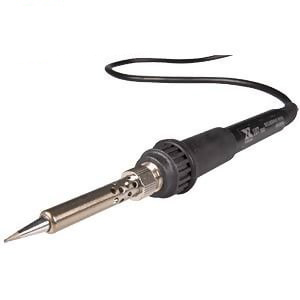
Soldering Electronic Components:
The most important tool in soldering the components is soldering iron itself. The tip of the iron is at 400oC and its tip can be replaced as required. Connect your iron to AC socket and wait till it gets hot enough. Then take a little soldering wire and touch at the tip, a smoke will raise indicating that iron is ready to solder. This little solder on the tip also helps the heat to flow from iron tip to joint. This process is called “tinning”
You must have a soldering iron stand, so you can place in it when not in use. Soldering should be done in place where there is ventilation. The smoke of solder wire is injurious to health
You should have a wet sponge so as to clean iron tip as required. Now as your iron is ready, grab it like a pen and touch the iron tip with both soldering wire and joint. The joint is the point where component lead and PCB track needs connection. Now hold the tip at the joint for 1-2 seconds until the solder is formed like a “mountain”. After 1-2 seconds the solder cools and you see mountainous like shiny solder. This soldering is good. While if you see like balls of solder then this is not good.
Soldering Precautions:
1- Some components are heat sensitive, so applying solder tip too long will damage the component like transistors
2- Some components are ESD (Electro Static Discharge) sensitive, so you have to earth your hands before touching or unpacking these components from their special ESD protective packing
What is Solder:
Conventional solder is alloy of tin and lead, 60% tin and 40% lead. Melting point 200°C. Modern solder is lead free and alloy of tin along other metals like copper and silver. Melting point 220°C. Covering a surface with solder is known as ‘tinning’ due to tin content of solder.
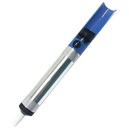
De-soldering:
A solder sucker is used to de-solder the components from board. Apply iron tip at the joint, now as the solder melts apply sucker to suck the molten solder. Copper braid is also good, it absorbs the molten solder into itself away from the joint. Apply heat from iron tip to the joint until solder melts then introduce copper braid to soak the molten solder and then remove the copper braid then iron tip.
The main difference between industrial grade and automotive grade components
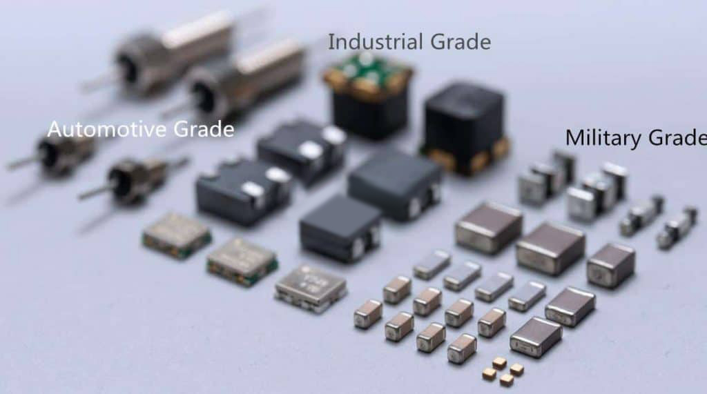
Automotive Grade vs Commercial Grade
The main difference between industrial-grade components and automotive-grade components is in the operating temperature range. Generally, the operating temperature range of industrial-grade components is -40°C to +85°C, while automotive-grade components are -40°C to +125°C. Furthermore, automotive-grade components have better performance, more robust temperature adaptability, and anti-interference capabilities than industrial-grade components.
This includes resistance to temperature limits, temperature differences, and other reliability, etc. The investigation found that the operating temperature range of some manufacturers’ industrial-grade components can also reach -40℃~+125℃ (such as ADI). The advantages of automotive-grade components are reflected in their performance and reliability. The main difference between them reflects the entire production, control, and testing links of the product.
1.Standard
Automotive-grade components are based on industrial-grade components and have stricter standards. ISO/TS 16949 standards and AEC standards have become the basic conditions for IC companies to enter the automotive industry chain.
1. ISO/TS 16949
The ISO/TS 16949 standard is a quality system management standard for the automotive industry developed based on ISO 9001: 2000. PPAP (Production Parts Approval Process) requires that automotive-grade components have detailed and complete data and documents. The PPAP document lists the production and quality assurance procedures required by the IC chip manufacturer.
PPAP is used to determine that the supplier has correctly understood all the requirements in the customer’s engineering design records and specifications during the actual mass production of parts and evaluates whether it has the potential to continuously meet these requirements, thereby ensuring the quality of the components.
2.AEC standards
The AEC (Automotive Electronics Council, Automotive Electronics Council) series standards that automotive-grade components mainly follow are AEC-Q100, AEC-Q101, AEC-Q001/Q002/Q003, etc.
AEC-Q100 is for active parts (microcontrollers and integrated circuits, etc.), mainly to prevent various possible conditions or potential opportunities for errors in products and guide suppliers to produce products that meet this specification during the development process. AEC-Q100 strictly confirms the quality and reliability of each application case. Also, it confirms whether the product datasheet, purpose of use and function description proposed by the manufacturer conform to the initially declared function and whether it can be used after multiple uses. Consistently.
This standard’s biggest goal is to improve the yield of products, whether in terms of product size, qualification rate, or cost. AEC-Q100 also specifies the requirements for IC devices in detail and also represents the requirements for product safety of automotive-grade device manufacturers. AEC-Q100 regulates a total of 41 tests in 7 categories:
(1) Group A- ACCELERATED ENVIRONMENT STRESS TESTS: A total of 6 tests, including PC, THB, HAST, AC, UHST, TH, TC, PTC, HTSL.
(2) Group B-ACCELER-ATED LIFETIME SIMULATION TESTS: A total of 3 tests, including HTOL, ELFR, EDR.
(3) Group C-Package ASSEMBLY INTEGRITY TESTS has six tests: WBS, WBP, SD, PD, SBS, and LI.
(4) Group D-DIE FABRICATION RELIABILITY TESTS has five tests: EM, TDDB, HCI, NBTI, and SM.
(5) Group E- ELECTRICAL VERIFICATION TESTS: A total of 11 tests, including TEST, FG, HBM/MM, CDM, LU, ED, CHAR, GL, EMC, SC, SER.
(6) Group F- DEFECT SCREENING TESTS has 11 tests, including PAT and SBA.
(7) Group G- CAVITY PACKAGE INTEGRITY TESTS: A total of 8 tests, including MS, VVF, CA, GFL, DROP, LT, DS, IWV.
The AEC-Q101 standard is aimed at discrete components and includes stress testing (inclusion testing methods) for separating semiconductor components.
AEC-Q001/Q002/Q003 standards are mainly guiding principles. AEC-Q001 mainly proposes the Parametric Part Average Testing (PPAT) method, a statistical method used to detect abnormal characteristics of outer semiconductor components and remove abnormal components from all products. AEC-Q002 is based on statistical principles, and it is a statistical yield analysis.
It provides component manufacturers with statistical techniques to detect and remove abnormal chip components. It is widely used to make early detection in the wafer and bare die stages. . AEC-Q003 is a characteristic guideline proposed for the typical performance of chip tea farmers. It is used to generate specifications and datasheets for products, processes, or packaging.
The purpose is to analyze data on mobile phone components and to understand this component and process. The properties, performance, and limitations of these components check the temperature, voltage, frequency, and other parameter characteristics of these components or equipment.
In each process of components production, there will be corresponding inspections of process quality. Simultaneously, a complete set of testing and screening of the components will be carried out after production. The test of industrial-grade components is generally performed at room temperature to inspect the various indicators shown in the product manual.
While the automotive-grade components are fully inspected, and inspection will be performed at -40~+125°C or equivalent temperature environment. At the same time, automotive-grade electronic components will be inspected according to the AEC Q100 standard, which greatly improves the product yield and product consistency.
2.Material selection and design
Generally, the main materials used in the production process of the device are Wafer, Lead Frame, Epoxy, Bond Wire, Mold Compound.
The main methods of material selection and design for automotive-grade devices are as follows:
(1) There is no difference in the material selection and design of industrial-grade components (components differences are reflected in the follow-up process and testing links).
(2) Consider better temperature adaptability of automotive-grade components, use better materials or better packaging designs, such as using ceramic packaging materials, adding heat sink designs, etc.
According to the research of ADI and TI, there are two methods in material selection and design. There is no evidence, which is better; it is generally according to product demand.
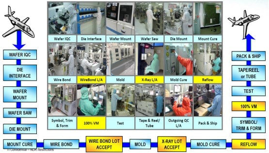
3.Production process and testing
The entire production operation has a mature and complete process from material quality inspection, components production, components testing, screening, and final storage. Compared with industrial-grade components, automotive-grade components are stricter in testing and screening due to their higher temperature adaptability, product consistency, and reliability requirements.
The components’ general production process is shown in the figure below. The yellow highlighted part indicates that there are more screening processes for automotive-grade components than industrial-grade components.
Military electronic components are an important cornerstone of weapons and equipment. With the development of science and technology and national defense construction, more and more components are used in weapons and equipment. How to query, count, exchange, process, and uniformly manage component information with many categories and complex parameters is an urgent problem faced by research and development units, production units, users, and management departments.
Scientific and standardized electronic components classification is an important basic work for enterprise informatization and improving the management level of electronic components. At present, all the major companies and industrial departments in my country manage their components according to their classification methods, either by function or process or by inheriting engineering experience, lacking a unified and standardized classification system and parameters measures.
This status is not conducive to data sharing, nor does it have good interchangeability between them. It also brings many inconveniences to the management of military electronic components (such as quality establishment, inspection, acceptance, evaluation, etc.).
Therefore, establishing a standard and reasonable military electronic components classification is the prerequisite and basis for standardizing military electronic components. The reasonable classification of military electronic components also plays a significant role in preventing the repeated research and development of similar products, the excessive expansion of product varieties, and the enhancement of product versatility and serialization.
At the same time, the scientific and effective classification of military electronic components will also play a guiding role in the standardization of civilian product classification. Since military electronic components are common for military and civilian use, scientific and effective classification is conducive to the integration of military and civilians. This can promote the conversion of more civilian products to military use, make full use of the industrial advantages of civilian products, and also help military electronic components.
Manufacturers open up the civilian product market and expand the production scale. Scientific and effective classification of military electronic components is also of great significance to the internationalization of general electronic components. These are the basis for improving the quality level and technical level of military electronic components.
2 Introduction to FSC
FSC is the abbreviation of Federal Supply Classification, that is, “Federal Supply Classification.” FSC was developed and adopted by the Office of the United States International Secretariat to classify the commodities in the federal government’s supply system and complete the classification of all commodities using “groups” and “classes.”
The structure of FSC adopts a secondary classification. The class number uses 4 Arabic numerals. The first two digits of the number indicate “group.” FSC currently has 78 groups from 10 to 99. These 78 groups are also called “Federal Supply Groups” (FSG), of which 21, 27, 33, 50, 64, 82, 86, 90, 92, 97, 98 are not currently used. “Groups” are sometimes referred to as “large categories.”
The last two digits represent the categories under the group, and 78 groups are further divided into 643 categories (April 2002 edition). For example, 5962, where “59” represents the group of “electrical and electronic equipment components” and “62” represents “microelectronic circuits.” The coding of classes is not continuous, which allows the classes under the group to be expanded when needed.
When searching in the “U.S. Military Standard Database,” you can search with the “59” group or the “5962” category number. The overall structure of FSC is arranged by class number. pay attention to the main items included and not included after the class number to clarify the scope of the class.
The FSC is also the basis for the US military standard classification because the US military standards are extensive and involve a wide range of specialties. The FSC classification is a reasonable classification method. Standard documents often change and develop. The changes and adjustments of the FSC classification and U.S. military standards interact with each other. These changes and adjustments reflect the rapid development of science and technology and the development of standards and management.
The classification of FSC brings convenience to the computer management of product information supplied and purchased by the US Federal. Furthermore, the classification also leaves room for further refinement of product categories.
3 FSC Electronic Components Related Group
FSC classification involves almost all industrial products, and group 59 is “electrical and electronic equipment components,” which we often refer to as electronic components group.
FSC60-Optoelectronic components are also regarded as electronic components. In addition, in group 61 and 62, some military electronic components are also included. If the special equipment and laboratory equipment of electronic components are considered, they are included in group 37 and 66. The names and descriptions of these groups are listed in Table 1.
FSC, as a federal supply classification of the United States, is a relatively reasonable classification for military electronic components. When the research and development unit of the General Assembly makes new product declarations, it uses the FSC method to expand the product categories with numbers. Firstly, classify the FSC categories, and then refine them layer by layer.
For example, 5962-01010101, where 5962 represents “integrated circuit,” 5962-01 represents “semiconductor integrated circuit” under integrated circuit, 5962-0101 represents “analog integrated circuit” in semiconductor integrated circuit, and 5962-010101 represents analog integrated circuit. The “amplifier” 5962-01010101 represents the “operational amplifier” in the amplifier. Of course, this method requires further optimization and needs to be approved by all user units.
American military standard MIL-STD
MIL-STD-469-1966 electromagnetic compatibility* design requirements for radar engineering
MIL-STD-463A electromagnetic interference and electromagnetic compatibility * definition of technical terms and unit system
MIL-STD-463A-1977 Electromagnetic Interference and Electromagnetic Compatibility* Definition of Technical Terms and Unit System
MIL-STD-462-1986 Interim Notice 5 (Navy) Special* Measurement of Electromagnetic Interference
MIL-STD-461C-10-1986 Part 10: Electromagnetic emission and sensitivity requirements for the control of electromagnetic interference surface Requirements for commercial electrical and electrical equipment (C3 category)
The electromagnetic emission and sensitivity requirements of MIL-STD-461C-9-1986 Part 9 for the control of electromagnetic interference are required for mobile power generation and related components in critical areas and uninterruptible power supply (UPS) and portable power supplies and applications. Electrical equipment (EMP) requirements (category C2)
MIL-STD-461C-8-1986 Part 8 is to control the emission and sensitivity requirements of electromagnetic interference. Requirements for tactical and special vehicles and mobile equipment (C1 category)
MIL-STD-461C-6-1986 Part 6 of electromagnetic emission and sensitivity requirements for the control of electromagnetic interference. Requirements for equipment and subsystems in submarines (A5 category). Part 7 of electromagnetic interference for the control of electromagnetic interference. Launch and sensitive requirements Requirements for auxiliary equipment and subsystems in non-critical areas on the ground (Class B)
MIL-STD-461C-5-1986 Part 5 is to control the emission and sensitivity requirements of electromagnetic interference. Requirements for equipment and subsystems in surface ships (A4 category)
MIL-STD-461C-4-1986 Part 4 of the electromagnetic emission and sensitivity requirements for the control of electromagnetic interference requirements for equipment and subsystems in-ground installations (fixed and mobile including crawler and wheeled vehicles) (Category A3)
MIL-STD-461C-3-1986 Part 3 is to control the emission and sensitivity requirements of electromagnetic interference. Requirements for spaceborne and missile-borne equipment and subsystems (including corresponding ground auxiliary equipment) (A2)
MIL-STD-461C-2-1986 Part 2 of electromagnetic emission and sensitivity requirements for the control of electromagnetic interference Requirements for airborne equipment and subsystems (including corresponding ground auxiliary equipment) (Class A1)
MIL-STD-461C-1-1986 Part 1 is the general requirements for the control of electromagnetic interference emission and sensitivity requirements
MIL-STD-461B Controls the emission and sensitivity requirements of electromagnetic interference
MIL-STD-461B-1980 Electromagnetic emission and sensitivity* requirements for the control of electromagnetic interference
MIL-STD-454G-1980 General requirements for electronic equipment standards
MIL-STD-4538(USAF)-1977 Radiographic flaw detection
MIL-STD-449D-1973 Radio frequency spectrum characteristics* measurement
MIL-STD-414-1957 Measurement inspection sampling procedures and tables
MIL-STD-413B-1969 Rubber O-ring Appearance Inspection Guide
MIL-STD-403B-1968 Preparation and assembly of rivets and screws for rocket and missile structures
MIL-STD-401B-1967 General test method for sandwich structure and core material
MIL-STD-291B-1967 Standard tactical air navigation (TACAN) signal
MIL-STD-290D-1976 Petroleum and petroleum products packaging
MIL-STD-285-1956 Attenuation measurement method of electromagnetic shielding room for electronic test
MIL-STD-280A-1969 Product grade Product interchange* Prototype and related term definitions
MIL-STD-255A AC and DC voltage
MIL-STD-220A-1959 Insertion loss measurement method
MIL-STD-210B-1973 Climatic limits of military equipment
MIL-STD-210A Climatic limits of military equipment
MIL-STD-209E-1976 Hoisting and tethering equipment
MIL-STD-202F-1980 Electronic and electrical test methods
MIL-STD-202C Test method for electrical components of electronic equipment
MIL-STD-200K-1974 preferred electronic tube
MIL-STD-196D-1985 Electronic Equipment Joint Model Nomenclature System
MIL-STD-190C-1977 Identification mark for rubber products
MIL-STD-188-313-1973 Line-of-sight transverse microwave and tropospheric scattering radio long-range communication subsystem design and engineering standards and equipment technical design standards
MIL-STD-188-322-1976 Long-range line-of-sight (LOS) digital microwave radio transmission subsystem design/engineering and equipment technical design standards
MIL-STD-188-317-1972 long-distance communication standard high-frequency radio communication subsystem design and engineering standards and technical design standards for equipment
MIL-STD-188-313-1973 Line-of-sight transverse microwave and tropospheric scattering radio long-distance communication subsystem design and engineering standards and technical design standards for equipment
MIL-STD-188-124-1978 General ground connection shielding for long-range tactical communication systems
MIL-STD-188-114-1976 Electrical characteristics of digital interface circuits*
MIL-STD-188-110-1980 Long-range/tactical general data modem equipment technical design standard
MIL-STD-188-100-1972 General technical standard for telecommunication systems and tactical communication systems
MIL-STD-188C(2)-1976 Military Communication System Technical Standard
MIL-STD-187-310-1976 Planning Standard for International Communication System Exchange
MIL-STD-177A-1969 Terminology for appearance defects of rubber products
MIL-STD-172B-1968 Liquid propellant container and color marking
MIL-STD-167-2(SHIPS)-1974 Mechanical vibration of ship equipment (reciprocating mechanical propulsion system and shafting)
MIL-STD-167-1-1974 Mechanical vibration of marine equipment (I environmental vibration) (II self-excited vibration)
MIL-STD-109B Quality assurance terms and definitions
MIL-STD-108E Electrical and electronic equipment enclosure definition and basic requirements
MIL-STD-108E-1966 definition and basic requirements for electrical and electronic equipment enclosures
MIL-STD-105E-1989 Inspection by attributes sampling procedures and tables
MIL-STD-105D-1963 Sampling inspection procedures and tables by attributes
MIL-STD-35-107(MI)-1976 Automatic engineering documentation system connector, socket, plug, and test point
MIL-STD-35-98A(MI)-1983 Variable capacitor for automatic engineering documentation system
MIL-STD-35-63-1974 Engineering file automatic preparation system semiconductor device chopper transistor
MIL-STD-35-60-1973 Engineering file automatic preparation system semiconductor device phototransistor
MIL-STD-35-75-1976 Engineering file automatic preparation system microwave/waveguide element
MIL-STD-35-44(MI)-1974 Automatic engineering document preparation system self-aligning machine
MIL-STD-792E(SH)-1986 Identification mark requirements for special components
MIL-ST
C4 Jinxiongdakejiyuan Huanguannan rd, Guanhushequ, Longhua district Shenzhen China
 sales@pcba360.com
 PCBA360
 +86-755-84717796
Certifications

Delivery


<

 Quote
Quote