
We provide functional circuit test services, and strongly request all PCBA
board doing FCT test before delivery, Pls try to provide testing file,
testing steps when you design or when you place an order.
ICT test device mainly tests the performance of all components. The aim is to check if there are problems or defects for boards in production. The test object is a semi-finished product, but the FCT fixture test object is a PCBA functional test. FCT fixture mainly to simulate the product working environment to verify the function of boards during working conditions. ICT test device and FCT fixture both are online tests.
FCT refers to the functional test in which PCBA connects the power. It includes voltage, current, power, power factors, frequency, duty ratio, position determination, LED lighting, LED color, sound recognition, temperature measurement and control, pressure measurement and control, precision micro motion control, FLASH, and EEPROM online programming. It refers to the operating environment (excitation and load) that provides simulation against the UUT.
1. For different control mode
(1)Manually control functional tests
(2)Semi-automatic control function test
(3)Fully automatic control function test
The earliest function tests are mainly automatic and semi-automatic. In order to simplify the design and reduce production costs, manual and semi-automatic are still used. With the technology development, to save production costs and improve production efficiency, most of the functional tests are fully automated.
2. For different controller
(1) MCU controller
(2) Embedded CPU controller
(3) PC controller
(4)PLC Controller
MCU controller is an embedded control, MCU and embedded CPU controller characteristics as below
(1) Test speed is fast
(2) Simple test steps
(3) Dedicated circuits and programs for data display and output
(4) Highly targeted test solution
(5) Easy to modify test software
PC controller is most widely used for FCT testing, and the main reasons are listed below:
PLC control is a common FCT development mode, and the focus is to control the induction part. However, the measurement function is weak. This is because PLC is for professional industrial control.
PCBA functional test is mainly divided into the following parts:
We donot have Minimum request for PCB Assembly order,Pls send your PCB file and bom list to Sales@pcba360.com , We will quote you shortly . Medical and military PCB projects is welcome.
PCBA Quote types:
1. Prototype PCB Assembly
2. Flexible PCB Assembly
3. PCBA Test ( ICT Test , FCT Test )
You can request full PCB manufacturing Price that XDF provide PCB,assembly, electronic components and testing, Also you can ask partial PCBA quote that you will provide some components by yourself, Our pcb assembly services is flexbile
Summary :
In the PCBA batch process, it is impossible to achieve 100% running status on the equipment and human operators. PCBA are good,so it requests all kinds of test equipment and test tools at the end of production. This leads to the other types of testing, such as ICT, AOI, X-Ray, Boundary Scan, to make sure all the circuit boards according to the design of various specifications and parameters.
FCT means providing a simulated running environment (excitation and load) to a UUT, making it functional in different design situations. Then, getting a range of different design situations to improve the UUT function. In short, it is suitable to load to the UUT, and the UUT output shows whether or not the board fits the design; it is called the PCBA functional test. FCT fixture is a fixture that simulates the finished PCBA.
The difference between ICT and FCT
ICT only tests if the PCBA is connected, short-circuited, LCP value, wrong orientation diode, and other semiconductor connections. The principle is to isolate other components then test a single or series-parallel group of components individually.
FCT is different; it is a functional test. It tests PCBA key components or output waveform through the relevant voltage or signal and determines if the values are within the acceptable range. Do not test against components. If the component fails, the functionality will be affected.
ICT has a universal tester. FCT can only be conducted according to the specific test requirements.
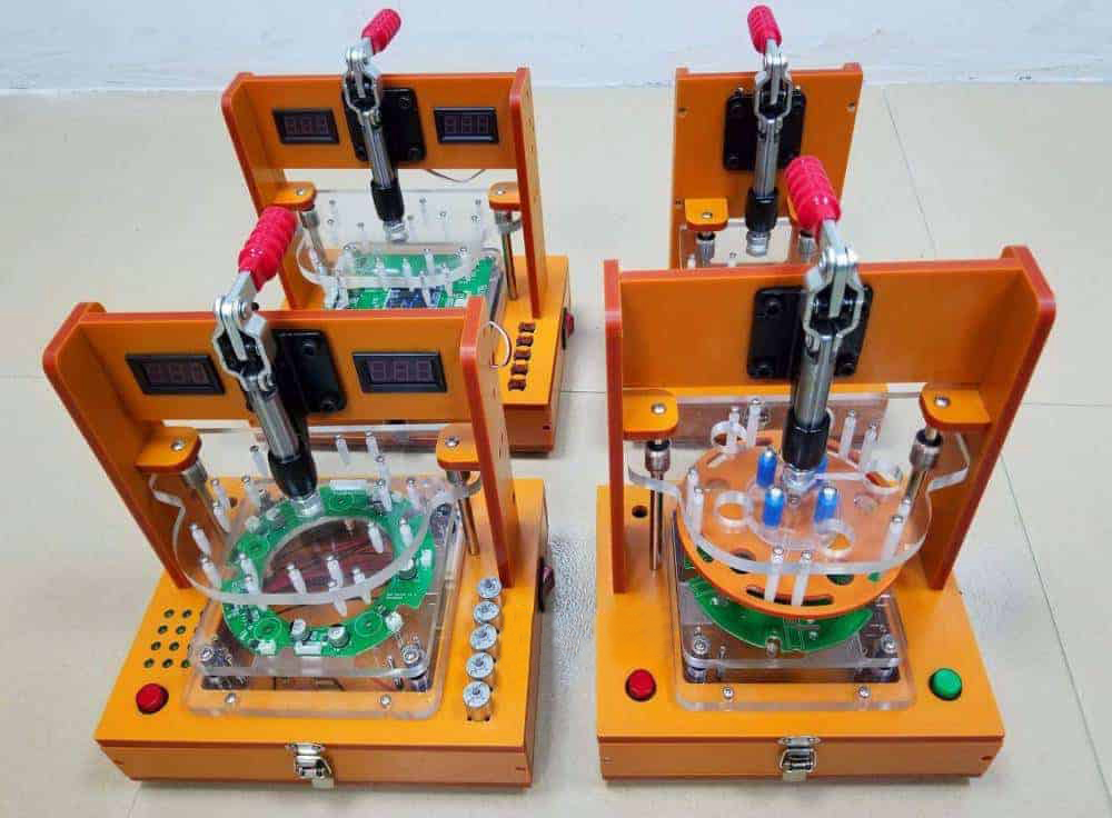
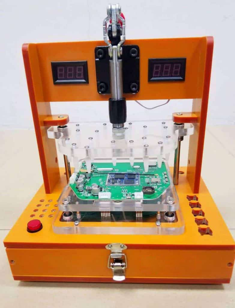
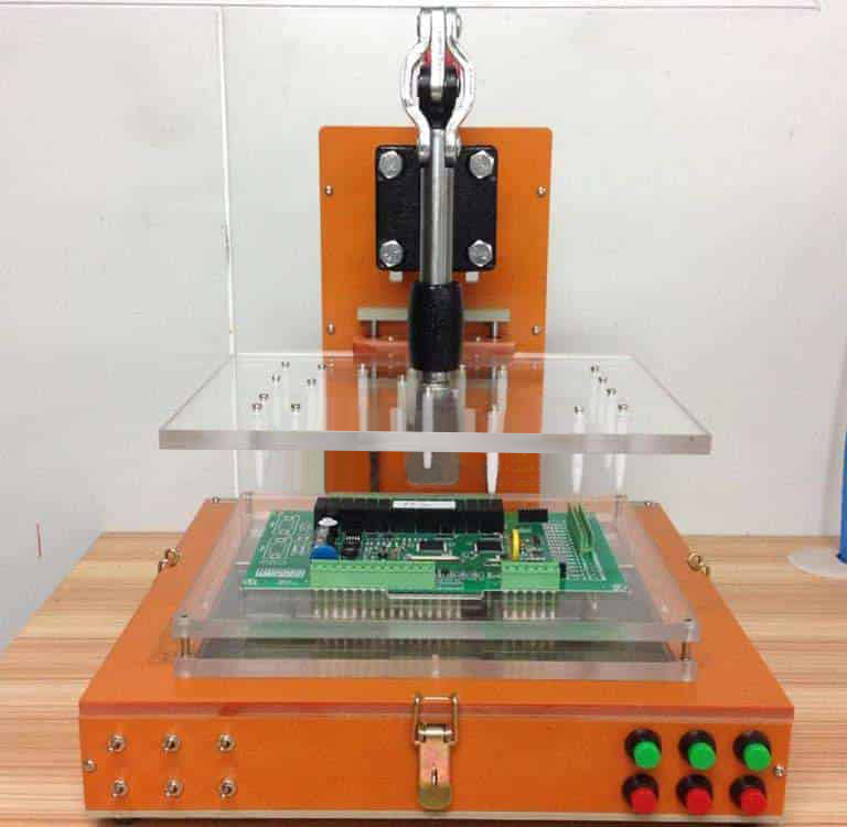
FCT fixture has electric/cylinder/manual quick clip, manual crank, and other mechanisms.
The materials can be imported bakelite, acrylic, aluminum alloy, iron, racing steel, or
fiberboard. They are then applied to the computer main board, LED lamp main board, LCD TV main board, communication equipment main board, and other electronic products.
The different control modes include manual control function test, semi-automatic control function test, and fully automatic control function test.

Quick clip Retainer Manual crank Pneumatic
FCT fixture production process:
3.1 FCT fixture raw material selection
3.2 FCT Fixture design work
3.3 FCT Fixture assembly and debugging
3.4 FCT Fixture inspection standard
3.5 FCT Fixture user caution
3.6 Fixture maintenance
4.1 Production department is responsible for CNC programming, CNC processing, and FCT fixture assembly.
4.2 The quality department inspect it according to the ordering list and FCT inspection standards.
4.3 Purchase department purchase raw materials and ask suppliers to provide the material reports, ROHS, and other documents.
4.4 The sales department will assess and promote the customer design requirements to production and assign inspection personnel to complete the inspection.
4.5 Engineering department is responsible for FCT fixture test circuit installation and debugging.
5.1 How to choose FCT fixture raw material:
| Item | Name | Material | Remark |
| 1 | Quick clip | big、Middle、Small | 304/305-HM/EM/CM |
| 2 | Retainer | big、Small | |
| 3 | manual crank | steel plate | |
| 4 | Pin board | Acrylic, bakelite | |
| 5 | bearing | Imported plating rod |
According to the test board and test requirements, select relay control, embedded microcontroller control mode, PC control mode, and PLC control mode. Then select the corresponding components after the mode is determined.
5.2 FCT fixture design according to clients document:

5. Other tools will be used to load the device
3.Fixture accurate positioning, and the docking of the connector should be smooth.
4. Reasonable fixture box layout,enough space for the assembly control system.
5.Correctspacing for fixture interface position.
6.Correct spacingfor optical fiber/MIC/SPK/SIM.
7.the locking of the fixture box should adopt the way of case buckle or pressure buckle to facilitate maintenance and replacement of parts.
8. The front of the fixture should be engraved with the name of the fixture: Song style, height 10mm, white color, middle position. Company LOGO, and date. Song body, 8mm height, white color, the bottom left corner position. Or paste the nameplate made by the company.
9.Keyword should specify the purpose and function of each key and switch.
10.Big bottom like: Emergency switch type, need to add white race steel protection. The height of the matchingsteel should not be lower than the highest point of switch bounce.
11.Function, lifetime, maneuverability, esthetic should be considered when design work. To achieve stable test and long service life, Beautiful appearance and humanized operation
12.Fixture should use the green and yellow cable with length 80-100cm. One side is alligator clamps, and the other side is clamp-shaped terminals.

its system is mainly divided into the following parts No matter how to test the PCBA:
This part contains PC, MCU, PLC, and other central processor components. Its main role is to control the whole test process and each step of the test content for evaluation and test results. It is the brain of the whole test system.
In the control center, consider the test board function, cost, test efficiency, and other control center system selection.
The control execution part comprises I/O components, induction, and execution mechanism of logical actions in the test process. The system builds a variety of testing environments to achieve the testing functions.
The control execution unit should be designed for safe use of the test board and can run reliably for an extended period.
The measurement part is mainly composed of board instruments. It mainly completes the collection of various analog or digital data in the testing process.
The final test result of each step and date storage should be in the data processing and output.
The results of data output are displayed visually and audibly. It will simplify the processing work of the facility operator.
5.3 FCT fixture assembly and debugging:
Structural partial assembly:
5.3. Non-functional acute angles should be chamfered R1 or 0.5×45°.
5.3.2. Black hexagonal socket screws are used for locking when using black bakelite, and stainless steel hexagonal socket screws are used for red dot wood and acrylic.
5.3.3. Each assembly step should be followed carefully and correctly to ensure the parallelism of the press board to the load board vertical board. This is to ensure the accuracy of the test fixture.
5.3.4. Select the correct test probe, test point normally is Pin ,Component pin using claw needle, if customers have special requirements can use other types of probe (round class). Probe contact 3.5mm-4.0mm, more test points can reduce the contact travel accordingly.
5.3.5.The positioning PIN is made of stainless steel, and the PIN head is processed into a ball shape, which prevents scratches to the test products.
5.3.6. Press bar to choose anti-static black steel bar, choose the flat press bar in the case of not hamper testing and collision, small position can be processed into a cone type
5.3.7. After assembly work it must debugging, correction point. The lettering on the panel is painted in a striking color for easy observation
5.3.8. Aquire spare parts for the components that can be easily damaged
4.1. Test good boards ten times and verify the fixture’s stability.
4.2. Use a good sample, repeat take few times, and verify the fixture’s accurate location.
4.3. Verify the test result of the fixture and if all requirements are met.
4.4. Check the safety of the operation button, power supply, and pneumatic control parts.
4.5. Check fixture stability and protection, especially special parts, such as external optical fiber, MIC, automatic card insertion device, adapter plate fixing module, pressing plate needle module, and other special switching devices.
4.6. Check whether the appearance meets the requirements, for example, damage, apparent scratches, etc.
4.7. Check whether the fixture labeling is standard and the high-pressure part and the easy-to-clamp part are labeled.
4.8. Check whether the cooling fan is operating correctly.
4.9. Verify the press bar is correct.
4.10. Check the position of the high parts relative to the sky plate milling grooves.
4.11. Verify the load plate milling groove is correct and whether the unmilling groove will press the parts.
4.12. Probe Pin working well or not, no Skew, no wipe
4.13. The tightness of the casing is moderate, without any loosening phenomenon, and the casing height is correct or not (down test compression is 2/3, up-test compression is 1/3~1/2)
4.14. whether the probe type is correct and whether the loading plate obstructs probe activity
4.15. Whether the clockwise machine is smooth and has no noise
4.16. Whether spare parts meet requirements and prepare the document according to the product list:
5. When inserting any test periphery, be sure to turn off the test fixture power to avoid damage to the test periphery. Use both hands to hold the two sides of the CPU. Align the CPU slot and insert the CPU’s golden finger from top to bottom. On the contrary, in selecting the application of both hands from the bottom up the CPU out.
6. When inserting the SD card, please be careful of the orientation. To eject the memory card, press the memory card first and then let the memory card reject itself.
7. Please be careful the cooling fan is running. Otherwise will damage the test system
8. Please pay attention to the display during the VFA test and make sure it is the correct paint and color. Also, please pay attention to whether the sound emitted by the buzzer on the board is normal.
9. Maintenance of FCT fixture:
10. The workers should wash the test probe every seven days to make sure the test probe is clean.
11. The workers should maintain the test probe, test cylinder, and electric control parts every three months.
12. Fixture should be free of dust. Add lubricating oil to the moving parts regularly.
C4 Jinxiongdakejiyuan Huanguannan rd, Guanhushequ, Longhua district Shenzhen China
 sales@pcba360.com
 PCBA360
 +86-755-84717796
Certifications

Delivery


<
 Quote
Quote